How Oil Furnace Thermostat Wiring Connects Heat and Air
For oil furnace electrical wiring, start by turning off power and checking the wiring diagram on your furnace. On a system with separate controls, the oil burner's Tw and Tr terminals handle the heat call. The blower control's R, C, G, and Y terminals handle thermostat power, fan control, and cooling. A smart thermostat needs a C-wire for steady power and must keep the burner and blower circuits separate. Do not join the two R circuits unless the equipment instructions specifically allow it.
I am Bill Scott, general manager of Smart Climate Solutions, with over 20 years of experience in heating and cooling installation and repair in the Pittsburgh area. In this guide, I will explain oil furnace electrical wiring so you can understand the connections and know when to call a qualified technician. Whether you are comparing an electric furnace installation, upgrading to a high efficiency furnace, or installing a new furnace, mastering control wiring ensures safe and dependable home heating.

Fundamentals of Oil Furnace Electrical Wiring and Power Supply
Every residential oil furnace relies on a dependable high-voltage foundation to power the burner motor, ignition transformer, and circulating air blower. Field wiring must strictly follow the National Electrical Code (ANSI/NFPA 70) and NFPA 31 standards for oil-burning equipment.
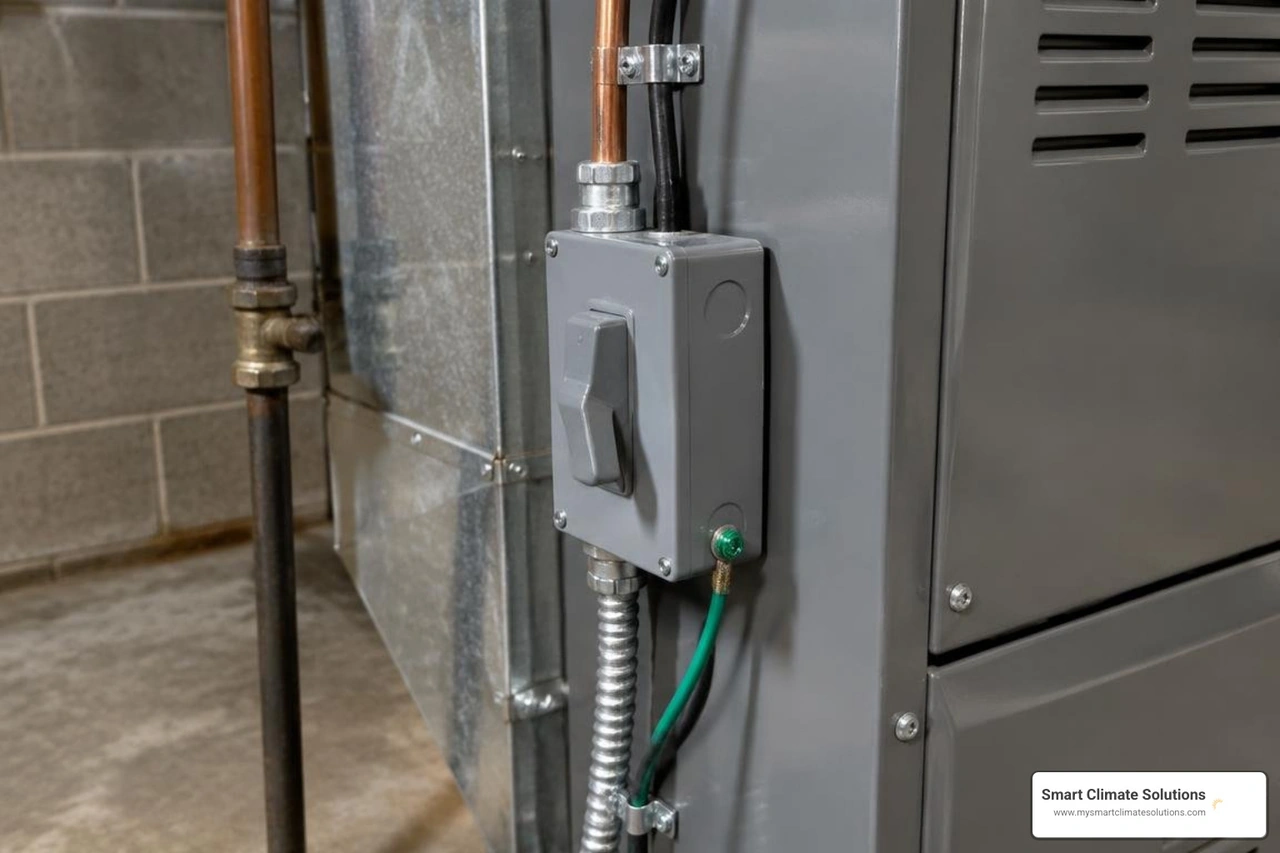
Standard residential installations require a dedicated 115 to 120 VAC, single-phase, 60 Hz electrical circuit. For highboy and lowboy configurations, technicians run a minimum of 12 AWG insulated copper wire rated for at least 75 degrees Celsius from the main electrical panel. Overcurrent protection is critical: smaller capacity units (around 72,000 BTU/h) generally specify a 15-amp fuse or circuit breaker, while larger output units (such as 119,000 BTU/h models) mandate a 20-amp time-delay fuse or HACR circuit breaker. Equipment grounding must be continuous and secured to the green grounding screw inside the furnace junction box to ensure electrical safety. You can consult the OIL-FIRED CENTRAL FURNACE Installation, Operation, and Service Manual for model-specific amp draws and breaker ratings.
Line Voltage Requirements and Polarity in Oil Furnace Electrical Wiring
Correct line voltage polarity is essential for modern electronic fan timer boards and oil primary controls. The incoming 120V line consists of a Hot (black) conductor and a Neutral (white) conductor. Connecting these backwards causes control boards to malfunction, prevents flame-sensing circuits from operating reliably, and creates dangerous shock hazards.
Field power connects directly to the factory pigtail wires inside the burner compartment junction box. Local safety codes require an emergency service disconnect switch installed in a readily accessible location, typically near the entrance to the utility room or right on the furnace cabinet. Technicians also maintain at least 24 inches of clear service space at the front of the furnace to allow safe access to high-voltage controls.
Safety Controls and Limit Switches
Oil heating systems utilize multiple integrated safety switches wired in series with the primary burner control:
- High-Limit Snap Disc Controls: Thermally activated switches positioned inside the warm air plenum that monitor internal temperatures. If airflow drops due to a clogged filter or blower failure, the high limit trips to interrupt power to the burner while keeping the circulating fan running to dissipate excess heat.
- Blocked Vent Shut-Off (BVSO) Device: A thermal or pressure-sensing switch installed on the flue collector or draft hood. It detects flue gas spillover caused by blocked chimneys or draft restrictions and cuts 24 VAC power to the burner primary control.
- Cadmium Sulfide (CAD) Cell Flame Sensor: Wired across the F-F terminals on the primary control. This optical eye monitors the burner flame. If ignition fails or the flame extinguishes during a cycle, the primary control locks out within 15 seconds to prevent unburned oil from flooding the combustion chamber.
When a safety switch opens, understanding the diagnostic sequence in our emergency furnace repair complete guide helps pinpoint whether the issue stems from an electrical fault, a blocked chimney, or overheating.
Low-Voltage Connections for Combined Heating and Air Conditioning
The low-voltage control side of an oil furnace operates on a 24 VAC Class 2 transformer. This transformer steps down 120 VAC line power to run the room thermostat, fan relays, safety interlocks, and air conditioning contactors.
When central air conditioning is added to an oil furnace, matching blower airflow becomes critical. While heating mode typically requires a moderate airflow to achieve an optimal temperature rise between 56 degrees F and 81 degrees F (or up to 85 degrees F on select models), cooling demands roughly 400 CFM per ton of air conditioning. Modern ECM variable-speed motors or 4-speed PSC motors allow technicians to select distinct speed taps for heating (often the red wire) and cooling (often the blue or black wire). Reviewing the L83UF, L83HF, L83BF, L83BR, & L83HR manual provides clear guidance on adjusting fan timer DIP switches and multi-speed taps.
Terminal Identification for Heating and Cooling Modes
Connecting a multi-stage or combined heating and cooling thermostat requires identifying each low-voltage terminal on the furnace control strip:
- R (24 VAC Hot): Delivers continuous 24V power from the transformer secondary winding.
- C (24 VAC Common): Provides the electrical return path to complete the circuit for smart thermostats and electronic controls.
- W (Heat Call): Energizes the oil burner primary control circuit to initiate combustion.
- Y (Cooling Stage): Routes 24 VAC to the outdoor air conditioning condenser contactor and energizes the high-speed blower tap.
- G (Fan Relay): Manually energizes the indoor circulating blower for continuous fan operation.
Using a 5-conductor (or 7-conductor) thermostat cable allows independent control over both heating and air conditioning functions. If the indoor blower fails to spin during cooling calls, you can refer to our guide on furnace blower motor replacement to troubleshoot capacitor and speed-tap connections.
Wiring Accessories to the Electronic Control Board
Electronic control boards and fan timers include designated line-voltage accessory terminals. The 120 VAC HUM terminal provides power to an external humidifier only while the burner is firing, preventing moisture from blowing through cold ducts. The EAC terminal provides 120V power to an electronic air cleaner whenever the circulating blower motor runs.
Never wire accessories directly to unused PSC blower motor speed taps. Unused motor windings generate counter-electromotive force and high auto-generated voltages that can destroy external electronic relays and humidifiers. Electronic fan timer boards also include DIP switches that allow installers to adjust fan-on delays (typically 60 seconds) and fan-off delays (between 60 and 120 seconds) to extract residual heat from the heat exchanger after combustion stops.
Two-Transformer Systems and Thermostat Compatibility
Many oil-heated homes feature a two-transformer setup. The air conditioning air handler or fan timer board contains its own 24 VAC transformer (powering Rc, C, Y, and G), while the oil burner primary control (such as a Beckett GeniSys or Honeywell unit) uses a separate built-in transformer supplying low voltage across its T-T (or Tw-Tr) terminals.
| System Feature | Single-Transformer System | Two-Transformer System |
|---|---|---|
| Power Source | One shared 24 VAC transformer | Two separate 24 VAC transformers |
| Heating Circuit | R and W connected to control board | Rh and W connected to burner Tw/Tr |
| Cooling & Fan Circuit | Rc, Y, G, and C on shared board | Rc, Y, G, and C on blower board |
| Thermostat Subbase | Jumper installed between Rh and Rc | Jumper removed between Rh and Rc |
| Relay Requirement | None for standard controls | Recommended isolation relay for smart stats |
| Heat Anticipator | Calibrated to combined circuit | Calibrated to burner control draw (e.g. 0.1A) |
Configuring Thermostats for Two-Transformer Operation
Standard thermostats come out of the box with a factory metal jumper or internal switch connecting the Rh (Heating 24V) and Rc (Cooling 24V) terminals. When connecting to an oil furnace with an independent burner transformer, you must remove this Rh-Rc jumper.

Failing to remove the jumper ties the two transformers together out of phase, which immediately blows a low-voltage fuse, burns out a transformer coil, or destroys the thermostat subbase. Once separated:
- Connect Rh and W to the oil burner primary control's Tw and Tr terminals.
- Connect Rc, C, Y, and G to the furnace blower control board.
If your oil burner fails to fire after replacing a thermostat, our troubleshooting guide on furnace not heating walks through identifying tripped primary controls and open low-voltage circuits.
Integrating Isolation Relays in Oil Furnace Electrical Wiring
Certain smart thermostats use solid-state triac switching circuits instead of mechanical dry contacts. These solid-state components can leak small amounts of voltage, confusing electronic oil primary controls and triggering false flame sensor lockouts or burner chattering. Furthermore, budget smart thermostats do not support separate Rh and Rc inputs.
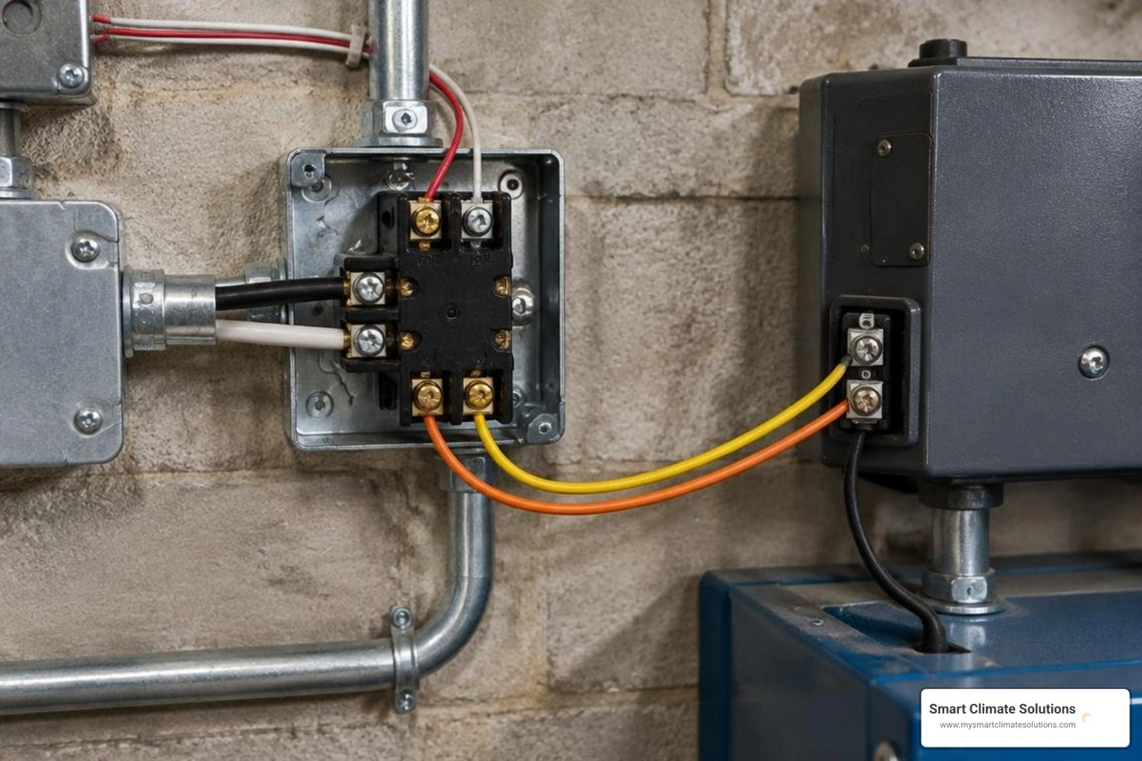
Installing an external isolation relay (such as the Honeywell / Resideo RA89A1074) solves this incompatibility:
- Provide 120 VAC line power to terminals 1 and 2 on the isolation relay.
- Connect the smart thermostat's W (heat call) and C (common) to the relay's low-voltage coil terminals (T-T).
- Connect the relay's dry contact output terminals (3 and 4) directly to the oil burner's Tw and Tr terminals.
The isolation relay acts as an isolated mechanical switch, closing the burner circuit safely without back-feeding current into the primary control.
Step-by-Step Guide to Wiring Modern Smart Thermostats
Upgrading to a modern smart thermostat improves comfort and energy management, but the electrical integration must be done systematically.
Running and Connecting the Dedicated C-Wire
Smart thermostats require a continuous 24 VAC power supply to operate their Wi-Fi radios and digital displays. Relying on "power stealing" over the heat wire can cause oil burner primary controls to pulse or fail to ignite during cold weather.
If your existing thermostat cable only contains 4 wires (R, W, Y, G), you have two options:
- Pull a new 18/5 or 18/7 solid copper thermostat wire from the furnace to the wall location.
- Install a manufacturer-approved add-a-wire power adapter module at the furnace control board to multiplex the G and Y signals, freeing up a dedicated conductor for the C terminal.
Connecting the Common wire directly to the transformer's ungrounded 24V secondary leg ensures uninterrupted power. If you need assistance running new thermostat cabling through finished walls, our certified team provides comprehensive HVAC Service and Repair across the greater Pittsburgh region.
Avoiding Common Wiring Mistakes and Component Damage
Low-voltage furnace circuits require careful handling during installation and retrofits:
- Shorted Transformer Secondaries: Touching the R wire directly to C or the metal furnace chassis will instantly blow the 3-amp or 5-amp blade fuse on the control board or burn out an unprotected transformer.
- Loose Wire Nuts in Blower Compartments: Furnace blowers generate continuous vibration. Always secure wire nuts on line-voltage and low-voltage motor leads with quality electrical tape to prevent dislodging.
- Reversed Line Polarity: Ensure the incoming black Hot lead and white Neutral lead are never swapped at the service switch or junction box.
- Mismatched Anticipator Calibration: When using mechanical thermostats on legacy oil burners, set the heat anticipator slider to match the exact primary control amp draw (typically 0.1 to 0.2 amps).
Frequently Asked Questions About Oil Furnace Wiring
Can I connect a smart thermostat to an oil furnace without an isolation relay?
If your smart thermostat has physical, separate Rh and Rc terminals and uses internal mechanical relays, you can connect Rh and W directly to the burner primary control's Tw and Tr terminals while powering the thermostat through Rc and C from the air handler. However, if the thermostat uses solid-state triac switching or lacks dual-transformer inputs, you must install an external isolation relay (such as an RA89A1074) to prevent electrical back-feed and control lockouts.
What should I do if my oil furnace lacks a C terminal for thermostat power?
Older oil furnaces without central air conditioning often lack a dedicated low-voltage terminal strip with an accessible C screw. In this scenario, identify the low-voltage 24 VAC transformer inside the burner control or fan center. Locate the secondary winding terminal that connects to ground or the common chassis circuit, and tap into that terminal using an approved spade connector to create your dedicated C-wire return path.
Why does my furnace blower run continuously after rewiring a thermostat?
Continuous blower operation after a thermostat installation usually points to one of three issues:
- The G wire is shorted to the R wire inside the wall or at the terminal block.
- The thermostat subbase internal jumper between Rh and Rc was left in place on a dual-transformer system.
- The manual fan switch on the high-limit control or thermostat interface was accidentally switched to the "Continuous ON" position.
Conclusion
Proper oil furnace electrical wiring ensures safe heating operation, accurate temperature management, and smooth integration with central air conditioning. Maintaining separate high-voltage safety circuits, isolating dual transformers, and providing a clean 24 VAC C-wire connection protects sensitive smart thermostats and primary burner controls from electrical failure.
Because oil furnaces combine 120V line power, high-voltage ignition transformers, and sensitive low-voltage safety loops, electrical service should always be handled according to local codes and manufacturer specifications. For homeowners in Pittsburgh, Canonsburg, Bethel Park, and surrounding areas, our team at Smart Climate Solutions brings over 20 years of field experience and 24/7 support. Contact us today for reliable maintenance or professional HVAC installation to keep your home warm and safe all winter long.